 Skip to content


symmetrical and unsymmetrical bending on a beam
| Code | FL160 |
Description:
- Symmetrical bending of a beam – also known as uniaxial bending – occurs when the load plane coincides with one of the main axes of the beam cross-section.
- The beam then deflects in the direction of the load and can be described by elastic lines.
- In unsymmetrical bending of a beam – also known as complex or biaxial bending – the main axes of the cross-section do not coincide with the direction of loading.
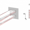
- To prevent torsion, the line of application of the load must pass through the shear centre. If it does not, the beam undergoes combined bending and torsion loading.
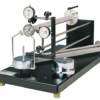
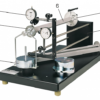
- FL 160is used to perform experiments relating to symmetrical and unsymmetrical bending and to combined bending and torsion loading.
- The beam under investigation is clamped into place on one end and loaded down at the free end.
- Two dial gauges record the horizontal and vertical deformation of the beam.
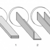
- The unit includes three beams with different cross-sectional profiles: I, L and U.
- The beam can be clamped with freedom to rotate in any direction.
- This enables investigation of loading along the main axis or of the general load case.
- An angle scale at the clamping point indicates the angular position of the beam.
- It is possible to adjust the load application point eccentrically, so that purely unsymmetrical bending or combined bending and torsion loading is investigated.
- The various elements of the experiment are clearly laid-out and housed securely in a storage system.
Technical Details:
Specifications:
- experimental unit for general and unsymmetrical bending of straight beams
- 3 beams: I, L and U profiles
- clamping flange of beam can be clamped in the pillar free to rotate in any direction
- clamping flange with angle scale to indicate the angular position of the beam
- eccentricity of load application points adjustable
- 2 dial gauges with bracket to record the horizontal and vertical deformation of the beam under load
- storage system to house the components
Technical Data:
- Aluminium beam
- deformed length: 500mm
- Eccentricity of load application point: 0…25mm
- Dial gauges:
- 0…10mm, graduation: 0,01mm
- Angle scale:
- 0…360°, graduation: 1°
- Weights:
- 1x 2,5N (hanger)
- 1x 2,5N
- 3x 5N
Dimensions & Weight:
- L x W x H: 700x350x400mm
- Weight: approx. 25kg
- L x W x H: 720x480x178mm (storage system)
Learning Objectives/Experiments:
- product moment of inertia (Iyz) and axial second moment of area (Iy, Iz)
- Bernoulli hypothesis
- symmetrical bending on a beam (uniaxial)
- with I-profile
- with L-profile
- with U-profile
- unsymmetrical bending (complex) on a beam with an L-profile
- calculation of the neutral fibres
- combined bending and torsion loading by way of eccentric force application
- determination of the shear centre on a beam with a U-profile
- familiarisation with shear flow (shear forces in a cross-section)
- comparison of calculated and measured values
Scope of delivery:
- 1 experimental unit
- 3 beams
- 2 dial gauges with bracket
- 1 set of weights
- 1 spirit level
- 1 hexagon socket wrench
- 1 storage system with foam inlay
- 1 set of instructional material
Features:
- symmetrical and unsymmetrical cross-sectional profiles: I, L and U
- combined bending and torsion loading by way of eccentric force application
Accessories:
- Optional: WP 300.09 Laboratory trolley
Due to the continuous development of our products, the goods supplied may vary in detail to that illustrated on this Website.

